Table of Contents
PIC18: Connecting to a PS/2 mouse
 In a previous article we saw how to connect to a PS/2 keyboard. Here we are completing topic by describing how a PS/2 mouse can be interfaced to a PIC micro.
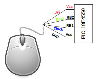
Connections remain the same; there are still four wires that carry +5V, ground, Data and Clock signals. Plus the same mini-DIN (male and female) connectors are used. Similar to the above article in the following articles clock line is blue and data line is yellow, but their position is inverted, so data traces are now on top.
Also the transmission protocol is the same, with clock pulses generated by the device (mouse in this case) and frames that consist of a start bit, 8 data bits, a parity bit and finally a stop bit. Data is still transmitted Least Significant Bit (LSB).
Physical connection to the PIC18
Instead of removing the male plug, as we did for the PS/2 keyboard, we are going to keep the mouse intact by means of a PS/2 female connector; with this approach the mouse could be easily swapped with another in case we would like to further experiment the protocol, for instance by studying Intellisense extensions (not discussed in this article).
Mouse data packets
The mouse keeps track of movement around the X-Y space and the state of its buttons by use of counters. The content of these counters are periodically sent to the host in the form a 3-byte movement data packet. The movement counters represent the mouse's offset relative to its position when the previous movement data packet was issued.
Movement data can be sent in Stream Mode, in which the mouse issues movement data packets when movement occurs or button state changes or in Remote Mode, where the host must poll the mouse to get movement data packets.
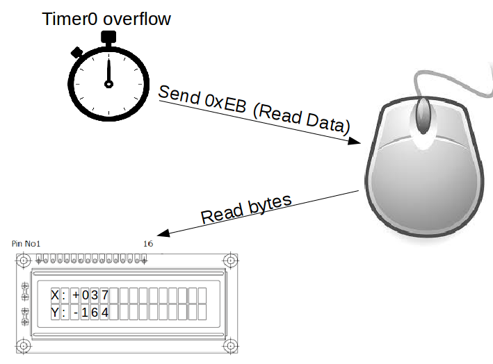
In this article we will use only Remote Mode; this operation mode is achieved by sending the command 0xEB (Read Data), which occurs everytime TMR0 overflows:
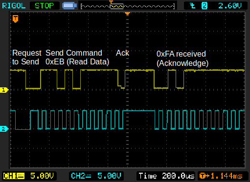
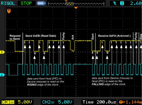
Here we can see an example trace where 0XEB command (Read Data) was issued by the PIC:
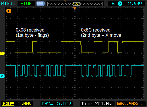
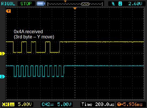
The mouse responds with an 'acknowledge' (0xFA) and then with the 3 bytes of the movement data packet, in this case 0x08, 0x6C and 0x4A:
The code
The most important routines are described here.
In Main, when TMR0 interrupt occurs ReadMouseValues routine is called, which, in turn calls the following subs:
PS2SendCommand is composed of the following steps:
- PS2RequestToSend:
- Bring Clock line low for at least 100uS
- Bring Data line low (50uS)
- Release clock line
- Wait for the mouse to respond and to bring clock line low again
- Clock line is low again
Now the mouse should start generating clock pulses; the host then issues a Read Data command (0xEB). As stated before:
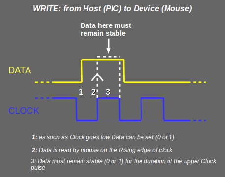
Data sent from the host to the device is read on the rising edge of the Clock
That means that Data signal has to be stable (0 or 1) before Clock signal rises and for the whole length of the up state of it:
- PS2SendData (0xEB):(with Clock line low)
- Reverse byte (data has to be sent LSB)
- Send Data bit (Carry)
- If bit = 1 increment PS2Parity file register
- Wait for the Clock to finish to go low and then to finish to go high (WaitPS2ClockPinLowHigh routine)
- Clock line is low again
- Repeat steps 2. - 3. eight times
The mouse expects to receive a parity bit:
- PS2SendParity: (with Clock line low)
- Send parity bit (get last bit of PS2Parity file reg)
- Wait for the Clock to finish to go low and then to finish to go high (WaitPS2ClockPinLowHigh routine)
- Clock line is low again
And finally we're releasing Data and Clock lines:
- PS2StopReleaseAck: (with Clock line low)
- Wait for the Clock to finish to go low and then to finish to go high (WaitPS2ClockPinLowHigh routine)
- Set Data pin as Input again
- Wait for Ack by device (Data low then high)
- Set Clock pin (and Data just to be sure) as Input again
- Clock line is now high
Now that EB (Read Data) is sent read first mouse byte (ACK = FA); we are not interested in this byte, which should be 0xFA.
This is how PS2MouseReadByte routine works:
- 1st bit (Start): We don't care to obtain this bit, which we know is '0', so let's wait for one turn the clock to go low and high:
- Wait for clock pin to go low (WaitPS2ClockPinLow)
- Wait for the Clock to finish to go low and then to finish to go high (WaitPS2ClockPinLowHigh)
- Clock line is now low
Now that's the part we are interested in, that is the mouse data byte; let's stress the following concept:
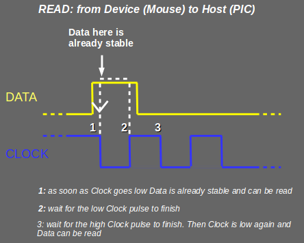
Data sent from the device to the host is read on the falling edge of the Clock
That means that Data signal is already stable (0 or 1) after Clock signal goes down:
- 8 Data bits :
- AcquirePS2DataBit (when Clock line is low Datum is stable: acquire it!)
- Wait for the Clock to finish to go low and then to finish to go high (WaitPS2ClockPinLowHigh)
- Clock line is now low: repeat eight times for the entire data byte
- ParityBit (we don't care to obtain this bit)
- Wait for the Clock to finish to go low and then to finish to go high (WaitPS2ClockPinLowHigh)
- Stop bit (we don't care to obtain this bit)
- Wait for the Clock to finish to go low and then to finish to go high (WaitPS2ClockPinLowHigh)
PS2DataByteFA (acknowledge), PS2DataByte1 (flags and buttons), PS2DataByte2 (X movement) and PS2DataByte3 (Y movement) are being assigned the above values and then finally displayed onto LCD.
Also displayed are mouse buttons pressed and movement overflow status.
