Table of Contents
PIC18: Ultrasonic sensor
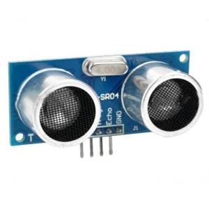 In this article we are going to experiment with an ultrasonic sensor, the HC-SR04; it seems quite known and common, especially in the Arduino community, maybe because it is quite cheap and simple to operate.
Wanna discover how we can use it to measure the distance of an object, by interfacing it to the Freedom II development board? Yes? Coool! So… let's get started!
HC-SR04 operation
The sensor comes with four pins:
- +5V Supply
- Trigger Pulse Input
- Echo Pulse Output
- GND
Triggering
The datasheet explains how to activate the Trigger pin and what it produces:
You only need to supply a short 10uS pulse to the trigger input to start the ranging, and then the module will send out an 8 cycle burst of ultrasounds at 40 kHz.
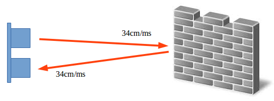
This train of ultrasound bursts travel forwards, until it finds an obstacle, and then backwards to the receiving end of the sensor; the echo pin will stay high for the duration of this travel back and forth.
Distance calculation
Ultrasonic of course means we're dealing with sounds, albeit inaudible to the human ear. The speed of sound is at around 340 m/s, which is equivalent to 34,000 cm/s or 34 cm/ms. So if the duration of the high pulse on the echo pin is, say, 2 milliseconds, that means that ultrasonic sound waves had to travel 34 centimeters to the obstacle for 1 ms and then 34 centimeters back to the HC-SR04. The length of the entire travel would be 68 centimeters, but the distance of the object will be half that measure:
In 1 ms the distance of the obstacle would be 17 cm and in 1 us it would be 0.017 cm; so which is the magic number that lets us convert the duration in us, measured on the Echo pin, to centimeters? Easily said:
x = 1 us / 0.017 cm = 58
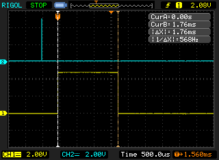
Let's say we capture 1.76 ms (1760 us) on the Echo pin (here below the capture shown on the scope):
Distance(cm) = 1760 us / 58 = 30 cm
A high 1760 us pulse on Echo pin means that the obstacle is 30 cm far away from the sensor.
Capture
Pulses on the Echo pin can be _captured_ by the PIC by configuring its CCP modules in … well, Capture mode, the other modes being Compare and PWM.
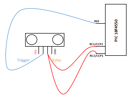
The CCPx pins on the 18F4550 are RC2(CCP1) and RC1(CCP2), which will be connected to the Echo pin of the sensor:
Let's read from the datasheet what happens when a capture event occurs:
15.2 Capture Mode
In Capture mode, the CCPRxH:CCPRxL register pair captures the 16-bit value of the TMR1 or TMR3 registers when an event occurs on the corresponding CCPx pin. An event is defined as one of the following:
- every falling edge
- every rising edge…
So this is the plan:
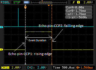
- CCP1 will be configured to capture a rising edge
- whenever that occurs TMR3 will be cleared and start to count
- CCP2 instead will listen for falling edge inputs
- in which case TMR3 will stop and its value will be saved into CCPR2H:CCPR2L registers
- that value will represent the duration of the high signal on pin Echo, which is proportional to the distance to the objrct
The code
The core of the program (main routine) is super simple; we are going to take measurements every second, by sending an input to the Trigger and waiting for the Echo. To achieve that an interrupt is generated by TMR0 overflow every 1 second, which sends the requested 10uS +5V to the Trigger pin of the sensor; the HC-SR04 will send the ultrasound bursts and the Echo signal back will be captured, via interrupt, by CCP1/CCP2.
Main
  btfsc REG_FLAG,TMR0         ; Is REG_FLAG,TMR0 (interrupt from TMR0 overflow) set?
  call SendTrigger            ; YES: call SendTrigger
  btfsc REG_FLAG,CCPInt       ; Is REG_FLAG,CCPInt (interrupt from CCP) set?
  call ReadEcho               ; YES: call ReadEcho
  bra Main
ReadEcho subroutine
The SendTrigger routine just sets RE0 (Trigger pin) high for 15 us; ReadEcho instead is activated whenever REG_FLAG,CCPInt is set in isr.asm as a consequence of a signal capture:
btfsc PIR1,CCP1IF	      ; A CCP1 rising edge capture?
bra CAPTURE1		      ; YES
btfss PIR2,CCP2IF	      ; a CCP2 falling edge capture?
goto EndIsr		      ; false alarm
CAPTURE2
  movff CCPR2L,CCPR2Low       ; Get low byte of captured time
  movff CCPR2H,CCPR2High      ; Get high byte of captured time
  bcf PIR2,CCP2IF	      ; Clear flag
  bsf REG_FLAG,CCPInt	      ; Set flag CCP in the custom register REG_FLAG, which is checked in main.asm
  goto EndIsr
CAPTURE1
  clrf TMR3H		      ; Zero count
  clrf TMR3L
  bcf PIR1,CCP1IF	      ; Clear flag
  goto EndIsr
Here when a rising edge is captured on CCP1 TMR3 is cleared and starts to count up, to measure the duration of the pulse length; when a falling edge is captured on CCP2 it means that the pulse has ended and we can copy the values of CCPR2x, which contain the values of TMR3x, that is the duration of the pulse.
Going back to main.asm CCPR2High and CCPR2Low are just rough values that need to be converted in order to get the distance of the obstacle.
Calculations
With a 5 MHz Fosc/4, there are 5,000,000 instructions per sec or 1 instruction every 0.2 us (1/5,000,000); TMR3 is prescaled by 8 in order to have less increments, which occur every 1.6 us (0.2 us * 8).
; CCP1_ON init:
IFDEF CCP1_ON
  EXTERN CCPR2High,CCPR2Low
  movlw b'00000101'
  movwf CCP1CON	            ; CCP1 module captures +ve edge
  bsf PIE1,CCP1IE	        ; Enable interrupts from CCP1
  movlw b'11110001'	        ; Timer3 enabled, 16bit write, internal osc, prescale 1:8
  movwf T3CON
  bsf INTCON,PEIE	        ; Enable PEIE (bit 6)
ENDIF
We said before that in order to get the distance we should divide the value in us by the 58; here we don't have microseconds, but rather 1,6 us increments, so the new magic number is obtained in this way:
x = 58 / 1.6 = 36.25
36.25 is the divisor that should be applied to the value of TMR3H:TMR3L registers in order to get the distance in centimeters.
How can we divide a number by 36.25? With assembly is not as simple as with a calculator. To start we could divide by 32, which can be easily accomplished with Shift Left Register commands; left-shifting a number is the same as dividing by 2, so if we repeat this last operation 5 times we effectively divide by 32:
ReadEcho
movlw .5		        ; divide values by .32
movwf shiftr_count
shiftr_again
bcf STATUS,C		        ; we want the Carry to be 0 right now
rrcf CCPR2High,F 	        ; shift right CCPR2High with Carry
rrcf CCPR2Low,F	        ; shift right CCPR2Low with Carry
decf shiftr_count,F	        ; is this the fith time we rotate right?
bnz shiftr_again	        ; no: shift right again
                        ; yes: raw data CCPR2High and CCPR2Low should be divided to .32 now
After the last manipulations CCPRHigh is actually 0, at least for distances under 2 meters, which we are going to use in this experiment; so we can skip it and focus only on CCPR2Low.
So far we got a value which is a little overrated and so we use the routine DivisionByX in math.asm to get a more consistent value:
movf CCPR2Low,W
call DivisionByX             ; We divided by .32, but to get a better result raw data should be divided by .36
movf quotient,W              ; So, we remove 13% off CCPR2Low (.36/.32=1.13)
subwf CCPR2Low,F
By taking 13% off of it, CCPR2Low should now contain the decimal value, expressed in centimeters, of the distance of the obstacle!
Yes, we did it!

