Table of Contents
PIC18: Connecting to a PS/2 keyboard
 With the advent of the USB protocol in the 90's many peripherals' manufacturers abandoned the previous protocols and connections to adopt it as a unifying standard; in the past printers mostly used parallel/Centronics ports, modems were serials, scanners could use SCSI interfaces, which often required a daughter board to be placed inside the cabinet of PC's, and mice and keyboards had to be connected to PS/2 ports. USB slowly emerged and unified all the connection needs in one single type of port and protocol stack; nowadays it is rare to encounter a new computer equipped with serial, parallel or PS2 ports.
Nevertheless PS/2 protocol is easier to understand and implement compared to USB, which has an entire protocol stack to be understood and implemented (material for a future article). So let's recover that old PS/2 keyboard we threw in the wastebin long ago and see how we can connect it to a PIC!
Wires and Pins
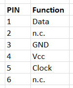
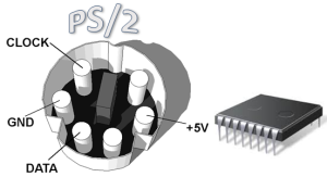
The PS/2 keyboard male connector is called mini-DIN and got six pins, two of which are not connected (n.c.), leaving us with four pins/wires to consider:
Using the pins of the mini-DIN male connector to connect to a PIC is a bit awkward, because they are very close to each other and they are closely surrounded by a round metal plate. It is simpler to cut the keyboard cable, separate the wires and solder jumpers onto them. Unfortunately wire colours are not standard; on some HP keyboards we can find Yellow (Clock), Red (Data), Brown (+5V), Grey (Gnd), while on some Logitech ones the colour scheme is Green (Clock), White (Data), Pink (+5V), Brown (Gnd).
So, in order to be sure to get the correct pin-to-wire combinations, once the cable is cut, we should definitely check the mini-DIN connector with a multimeter, touching the leads one by one and probing the associated wire.
Make and Break codes
As soon as a key is pressed two distinct signals originates from the microcontroller on the keyboard, clock and data.
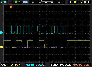
Here (and in the subsequent screenshots) clock line is blue and data is yellow. A PS/2 communication is serial and can be bi-directional, usually from the device (keyboard) to the host (in our case the PIC), but also the other way; we will see both type of communication in action.
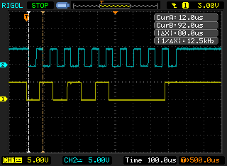
Data and Clock lines are are high when no communication takes place (idle). Clock pulses are generated by the keyboard only when a transmission occurs, at a measured frequency of around 12.5 kHz, the accepted range being 10-16.7 kHz:
The keyboard is free to send data to the host when both Data and Clock lines are kept high. The keyboard will take the Data line low (Start bit) and then start generating the clock pulses on the Clock line. Each bit is sent on the Data line in series with the following order:
Start bit ⇒ 0…7 data bits ⇒ Odd parity bit ⇒ Stop bit
Data sent from the device (keyboard) to the host (pc) is read on the falling edge of the clock signal; data is transmitted Least Significant Bit (LSB) first, so bits have to be reverted on the host in order to obtain the correct key code.
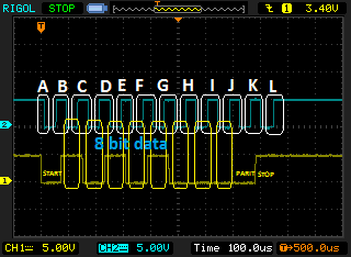
The following picture explains better the Make code that 'q' key generates:
A: Start (0)
B - I: eight Data bits
J: Odd Parity
K: Stop (1)
L: line idle
So the sequence of bits that was sent from the keyboard was 10101000; we know it's LSB, so we invert it and get b'00010101' or 0x15 which corresponds exactly to the make code for 'q'.
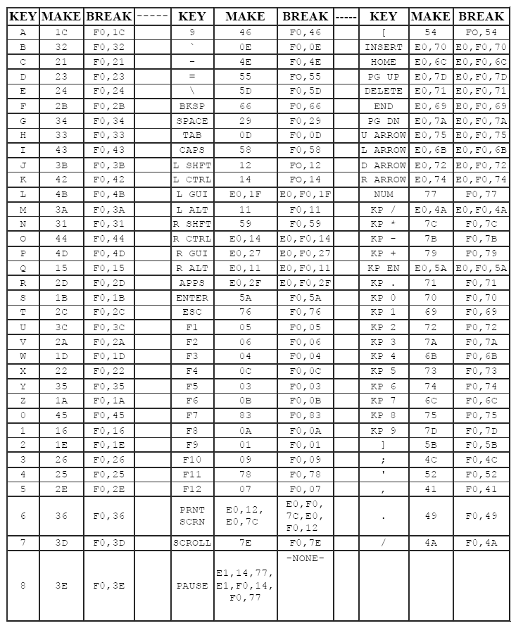
Here's the complete reference for Scan Set 2 make/break codes, which is the set to consider for PC AT keyboards (all values are hexadecimal):
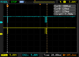
The Break code is generated when the key is released. Here on the right of the pic we see the two distinct codes that comprise the break code; generally the first is 0xF0 and the second is the Make code repeated:
Connecting to the PIC18
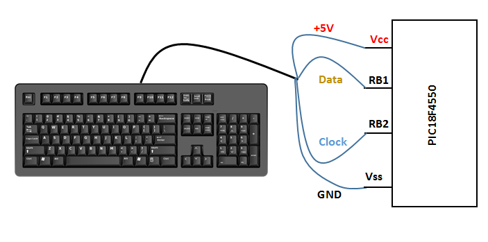
As said before, Data and Clock are open-collector, so they both need a resistor to stay at +5V; to do that we are going to use the internal pull-up resistors of PORTB. The keyboard wires will be connected in this way:
The code
Receiving key strokes
Whenever a key is pressed clock and data pulses are generated by the keyboard and intercepted by RB1 and RB2 pins; in particular clock falling pulses raise interrupts on RB2/INT2 which mark the beginning of the reception (A on the image above) for the PIC, by calling ReadMakeCode routine.
We know that the first bit sent by the keyboard is a Start bit, nothing we are interested in: so we simply discard it and wait for the clock pulse to finish, that means waiting for the clock line to go low and then high (B on the image). This is the purpose of _WaitLowHighPS2Clock_ routine:
WaitLowHighPS2Clock
  btfss PS2ClockPin    ; Wait for the LOW clock pulse to finish
  goto $ - 2           ; No, still low. Go back to previous instruction
  btfsc PS2ClockPin    ; After low edge wait for the HIGH clock pulse to finish
  goto $ - 2           ; No, still high. Go back to previous instruction
  return
The end of the routine marks the beginning of the clock falling edge, when the next bit can be safely acquired.
Then we need a loop to get eight data bits, the _juice_ we're looking for: every acquired bit is tested in AcquirePS2DataBit routine to see if it's '1' or '0', by checking the carry:
AcquirePS2DataBit
  bcf STATUS,C         ; Carry = 0
  btfsc PS2DataPin     ; Test incoming PS2 data bit
  bsf STATUS,C         ; Incoming bit is '1': Carry = 1
  rrcf PS2Data         ; Insert Carry into PS2Data, rotate right register
  return
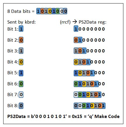
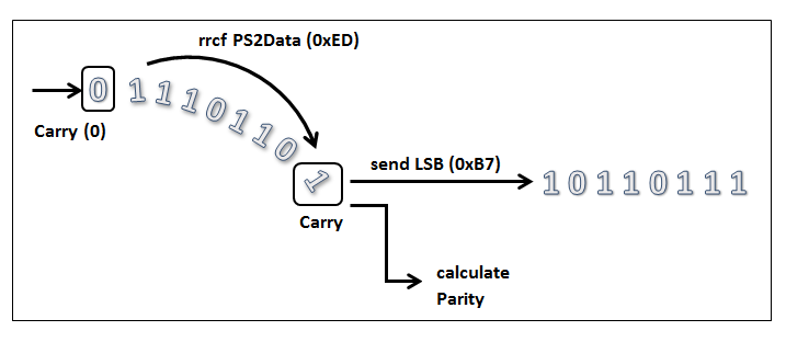
This value is then cleverly right-shifted into PS2Data register, the cleverness here being that, by doing so, PS2Data ends up loaded with the already inverted value that represents the correct Make code. Let's see how that is achieved:
As we can see every data bit sent by the keyboard, starting from the leftmost one, is right shifted into PS2Data, effectively ending in the inversion of the original sent byte and resulting in the correct Make code for the key pressed.
Unfortunately Make codes don't match with ASCII codes, so the value has to be translated by means of a look-up table, as done by PS2DisplayTable routine (for an explanation of look-up tables see this previous article on 7-segment displays).
We skip Parity and Stop bits as we did for the Start one and, finally, the translated value is displayed onto LCD; after the Stop bit there is a delay of 150ms, in order to avoid getting the break codes (as seen in above there is a delay of 129 ms between the beginning of the make code and the end of the break code).
This is the end of how the PIC manages a single key reception.
Lighting up LEDs on the keyboard
As already said communications can occur also from the host (PIC) to the device (keyboard); in this way the PIC is sending one or more commands to the keyboard. There is a bunch of commands that the keyboard can accept and they vary from setting Typematic Rate/Delay to reading its ID and some more. Here we want the PIC to send a command to light up the Num Lock, Caps Lock and Scroll Lock LEDs.
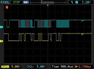
The following image represent an example of this communication in action, when a single command is sent:
The first thing the host has to do is telling the device it has something to send; this is done by:
- pulling Clock low for at least 100 microseconds
- applying a “Request-to-send” by pulling Data low, then release Clock
It's the task of the PS2RequestToSend routine:
PS2RequestToSend
  ; 1) Bring the Clock line low for at least 100 microseconds:
  bcf TRISB,2			; Set Clock pin as Output
  bcf PS2ClockPin		; Set Clock down
  movlw .100
  call usDelay		; Wait
  ; 2) Bring the Data line low:
  bcf TRISB,1			; Set Data pin as Output
  bcf PS2DataPin		; Set Data down
  movlw .50
  call usDelay		; Wait
  ; 3) Release the Clock line:
  bsf PS2ClockPin		; Set Clock up
  bsf TRISB,2			; Set Clock pin as Input again
The PIC has also to keep Data low as long as the keyboard responds and starts generating clock pulses. Even in a host-to-device communication it's always the device's task to generate the clock signal.
  ; 4) Wait for the keyboard to respond (wait for the device to bring the Clock line low)
  btfsc PS2ClockPin	        ; Wait for the HIGH clock pulse to finish
  goto $ - 2		        ; No, still high. Go back to previous instruction
After the keyboard has brought the clock line low it should start to generate regular clock pulses.
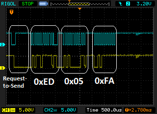
Here we see:
- the Request-to-Send sequence
- the Clock pulses by the keyboard
- the first _command_ sent (0xED - set/reset LEDs) by the PIC
- an _Ack bit_ by the keyboard
Some keyboards (e.g. IBM) require a delay of 2 ms after 0xED, otherwise they won't send an Ack.
The first command above (0xED) needs two things:
- to be sent LSB
- an added odd parity bit
It is to be noted that Data sent from the host to the device is read on the rising edge, contrary to what we saw before, from device to host.
Routine PS2SendData takes into account all those requirements; the LSB transmission is obtained by copying the command to be sent into PS2Data and then by right-rotating this register and evaluating the 'expelled' Carry. The same Carry is then cleared before reinjecting it into PS2Data:
The evaluation of the Carry is functional also to the calculation of the odd parity; infact when Carry = 1 the counter PS2Parity is incremented. This counter has been previously initialized to 1 in PS2RequestToSend routine; odd parity is then equal to the value of PS2Parity rightmost bit (bit 0), as seen in the PS2SendParity routine:
PS2SendParity
  ...
  movlw .1
  andwf PS2Parity			; Get bit 0 of PS2Parity
  bnz PS2Parity1			;
  bcf PS2DataPin			; PS2Parity,0 = 0
  goto EndPS2SendParity
  PS2Parity1
  bsf PS2DataPin			; PS2Parity,0 = 1
  EndPS2SendParity
After that it is necessary to orderly end the transmission; PS2StopReleaseAck is more than happy to accomplish that simple task.
The 0xED command needs another byte as a parameter, that specifies the state of the keyboard's Num Lock, Caps Lock, and Scroll Lock LEDs, where:
bit 0 - Scroll Lock
bit 1 - Num Lock
bit 2 - Caps Lock
In the example bit 0 and 2 are sent (0x05), in order to turn Scroll and Caps Lock on.
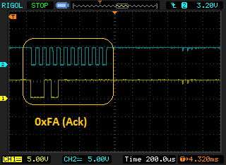
The last byte seen, 0xFA, is an ack byte sent by the device, a common response that normally follows host commands:
The scheme of the entire three-byte communication:
In the code, freely available at the bottom of the page, the pression of buttons BT1, BT2 and BT3 turns on Scroll, Caps and Num Lock respectively.
See here how it all works:


