Table of Contents
PIC18: I2C EEPROM dump via RS-232 serial
 In this project we are going to implement two different buses to get data from and to a PIC18: serial RS-232 and I2C bus. For an intro to I2C please see Wikipedia; the scenario that was implemented below is the one in which the PIC operates in _master mode_.
The project was tested using the wonderful demoboard Freedom II (more info here and the integrated 24LC32A EEPROM.
In particular we are going to:
- let the PIC receive serial data (using interrupts) from a PC
- send it onto 24LC32A I2C EEPROM and have it saved there
- then read ALL the I2C EEPROM data (memory dump)
- and finally send it back to the PC via serial
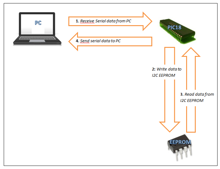
which, graphically and from the PIC point of view, could be represented like this:
So let's start with the first part of our program.
Receive serial data using interrupts
Configuration for the serial connection is set in SERIAL_ON init, which is in main.asm; the comments in the code should be quite self-explanatory, but basically it says we want 9600 bps, 8 bits data, asynchronous mode. Those are the values that have to be set also in the terminal program on the PC (under Linux gtk-terminal can be used). Since we don't want the PIC to continually poll the serial connection we need to use interrupts; to do this the following bits have to be set:
bsf INTCON,PEIE        ; Enable PEIE (bit 6)
bsf PIE1,RCIE	         ; Enable RCIE (bit 5) of PIE1 register, for serial RX
Now that the PIC is ready to receive serial communications, let's see how to handle those interrupts in the Interrupt Service Routine in isr.asm. Here things are quite simple; they have to be, because ISRs have to be as quick as possible: just the time to set a flag or two and then soon back to the main, otherwise there is the risk not to catch other important interrupts. So, when an interrupt occurs from serial reception (PIR1, RCIF flag set) the flag REG_FLAG,RBInt is set, which will be handled in main.asm:
btfss REG_FLAG,RCSer	; Check REG_FLAG,RCSer bit
<line skipped>
movf RCREG,W		; REG_FLAG,RCSer is set; copy RCREG into W
After the last line, RCREG, which holds the received serial data is copied to W.
Serial data viewed on the oscilloscope
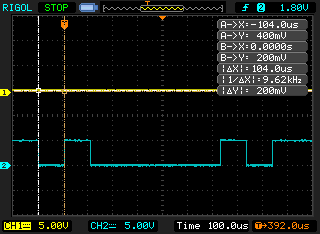
If we connect the probe of an oscilloscope to the RX pin of the PIC (RC7 for a 18F4550) and press capital 'A' on the terminal program on the PC, that's what we would see on the scope's display:
To get something useful on the display the scope must be setup properly before capturing the signal.
We said before that the desired baud rate is 9600bps; that means that the line can switch states 9,600 times per second, so each bit has the duration of 1/9600 of a second or around 104 uS; so the time division on the scope should be set to 100uS. Then we are going to set a trigger to catch when the signal changes: rising or falling edge is not important, the voltage was set to 1.80. With those settings we should be able to capture the incoming serial data. And indeed the cursors (the two vertical lines) tell us that a bit is 104 us and the frequency is 9.62 kHz or around 9600 bps.
Now how do we interpret that signal? First of all, between the PIC and the PC there is a MAX232 chip, which converts RS-232 voltages to signals suitable for use in TTL (0-5V); this chip has internal pull-up resistors connected to the input/output pins that go into RX/TX pins on the PIC. So, the first voltage level on the left represent the 'idle' state of the line.
Here's an extract from the PIC datasheet:
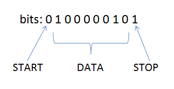
The string of bits on the display reads: '0 1 0 0 0 0 0 1 0 1'; the first '0' is the serial START bit; then we have '1 0 0 0 0 0 1 0', which are the data bits and eventually there is also an ending '1' which is the STOP bit (and then the line stands idle).
The datasheet says that “the EUSART (serial module) transmits and receives the LSb first”; so the first data bit on the left ('1') is actually the Least Significant bit and should go to bit 0, the second data bit on the left ('0') should go to bit 1 and so on; in practical we have to reverse the order of data bits to see the actual data sent from the PC.
Finally we got '0 1 0 0 0 0 0 1 which is indeed the ASCII code for capital 'A'!
Using Bash to send data to the serial port
Bash can be used instead of a terminal program; this can be easily accomplished in this way:
~$ stty -F /dev/ttyUSB0 9600
~$ echo A > /dev/ttyUSB0
or to output an entire file:
~$ cat file.txt > /dev/ttyUSB0
Now we want this data to be saved into I2C EEPROM; next paragraph shows how to do it.
Send data to I2C EEPROM
EEPROMs are memories than can hold data even when the power is disconnected. They come in different sizes, which are specified in Kbits, not KBytes; that means that a 24LC32A EEPROM (the one we are going to use) holds 32 Kbits / 8 = 4 KBytes of data.
As for I2C, it is a two-wire protocol, one wire carrying data (SDA) and the other the clock (SCL). In general write communications by a I2C master work in this way:
- I2C master generates a START condition, to tell that it has something to send onto the bus
- it places the address of the slave device (CONTROL byte) it wants to contact on the bus in write mode (more about this below)
- then it outputs the ADDRESS byte(s) of the register/location on the device it wants to write to
- it sends a DATA byte to be written
- followed by a STOP conditon
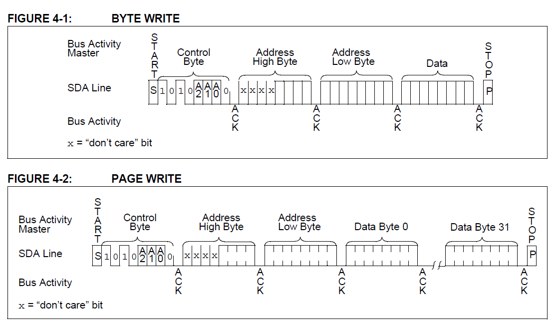
Now this is called a Byte Write in the datasheet; it is quite an inefficient method of transmitting large quantities of data, because only a DATA byte at a time can be sent. With Page Writes more DATA can be sent before sending a STOP:
See the two address bytes, high and low? They are needed, because only 12 bits allow to reach all 4K locations (2 ^ 12 = 4096). Furthermore the size of a page write for a 24LC32A EEPROM is 32, that means that up to 32 bytes can be transmitted before sending a STOP; it's important to note that page write sizes vary with the different EEPROMS (for instance it's 64 bytes for a 24LC128), so, as always, the datasheet is our friend. A page writes size represents the dimension of temporary buffers of the EEPROMs; data is first written to those fast buffers and then, after a STOP command, permanently saved into the internal memories of the EEPROMs.
Ok, so now what we want our code to send data to the EEPROM in 32 bytes batches, to take advantage of page writes; that may sound simple, but a few aspects need our attention and care:
- a counter has to … well, count up to 32 to mark the end of a page write
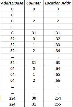
- a starting low address byte has to be provided, to form the base to which the counter adds up its values and then it has to be incremented; let's see it in action in the next figure:
As we see in the image, while the counter rolls over from 31 to 0, AddrLOBase is incremented by 32; that lets us reach all low EEPROM locations, from 0 to 255 (remember, the 32 counter serves to exploit page writes) and fills the low address byte.
But how can the other locations (from 256 to 4095) be accessed? Time for other requirements:
- a high address byte, which should be incremented by one whenever the starting low address byte rolls over from 224 to 0 and that happens if we add 32 to 224
- a maximum address byte which holds the highest reachable address location (4095)
The process should end when that last addressable location is reached or when a button on the demoboard is pressed.
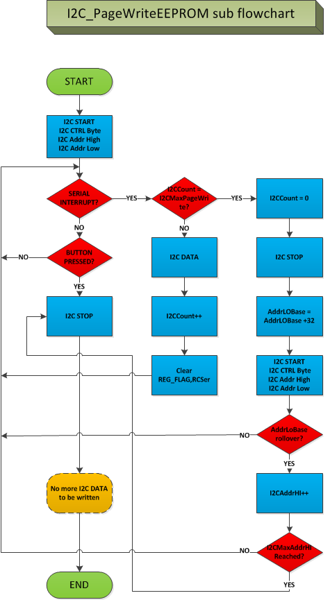
So, to sum all things up, the flowchart of the program could be represented in this way:
The above flowchart represent the (almost) entire subroutine I2C_PageWriteEEPROM, which lives in i2ceeprom.asm; the sub in there is heavily commented and we make use of branch instructions that we saw in a [previous article](https://www.t3ch.it/pic18-branch-instructions).
I2C data writes viewed on the scope
To catch I2C wave forms on the scope time/div should be setup at 10 us; that's because we are using a 100KHz frequency, with 1 cycle taking 1/100,000 seconds, 0.00001 seconds or 10 us. Channel 1 will show SDA (data - RB0 pin) line, while channel 2 will be the SCL (clock - RB1 pin).
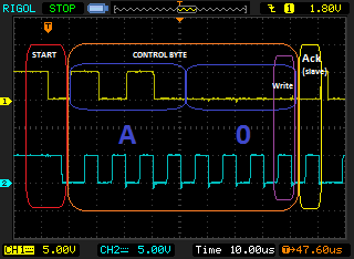
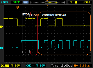
Here we see the START condition and the CONTROL byte:
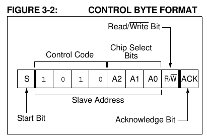
The SDA transition from high to low while SCL is high marks a START condition; then the Control byte (device address) follows, with the last bit indicating wheter the PIC is performing a Write or Read operation (write, in this case). The first 4 bits of the control byte (Control Code) are fixed, while the next 3 (Chip Select) can be changed to address up to 8 different EEPROMs (2 ^ 3 = 8):
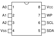
The address of an EEPROM can be changed by hardwiring its A0, A1 and A2 pins to Vcc:
Since names here can lead to confusion, it's important to underline that A0, A1 and A2 denote only the pins of the EEPROM, not control byte addresses.
At the end of the Control byte an ACK is generated by the slave (EEPROM), indicating that it got the data correctly: the PIC, acting as a master in this communication, leaves the bus idle; the slave keeps the line down (ACK is active low).
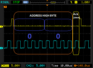
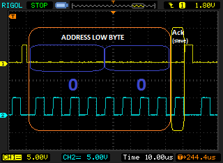
Then 2 bytes are sent with the HIGH and LOW Address byte of the EEPROM location to write to (slave acks both):
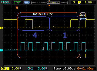
Capital 'A' is written on the serial terminal; it generates an interrupt which is handled in the code by writing its ASCII value (0x41) on the EEPROM location:
When all EEPROM locations are written or BT1 on the Freedom II is pressed a STOP condition is generated; the SDA goes from high to low while SCL is high:
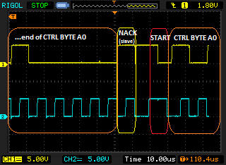
The next START and control byte sent above are the implementation of what is described in the datasheet as Acknowledge Polling:
“After the STOP condition the device has to write the data from its cache to its internal memory. The device will not acknowledge during this internal write cycle; this can be used to determine when the cycle is complete. This involves the master sending a start condition followed by the control byte for a write command (R/W = 0). If the device is still busy with the write cycle, then no ACK will be returned. If the cycle is complete, then the device will return the ACK and the master can then proceed with the next read or write command.”
And indeed the EEPROM sends a NACK, because it hasn't finished writing data to its internal circuits. I counted a little more than 30 NACKs before the EEPROM sent an ACK.
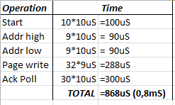
The datasheet specifications say that a page write takes a maximum of 5 ms; let's see how much time it takes the whole process:
An entire page write, from Start to Ack Poll included, took less than 1 ms.
Sequential read I2C EEPROM data
Now we want to read the entire content of the EEPROM; what distinguishes a read operation from a write one is the LSb of the Control Byte: if it's a '0' then a write operation is performed, while if it's a '1' a read is done. So, as we saw before, the control byte with address 0xA0 identifies the EEPROM device address and the fact that we want to write to it; the control byte 0xA1 is the read device address of the same EEPROM. But whenever we tell the EEPROM that we want to read it we somehow lose control of the process, because after that command, we cannot specify the address location (Address High and Low bytes) we want to access. In the datasheet this is called a Current Address Read and it is explained in this way: “The 24XX32A contains an address counter that maintains the address of the last word accessed, internally incremented by ‘1’. Therefore, if the previous read access was to address ‘n’ (n is any legal address), the next current address read operation would access data from address n + 1.”
To specifiy the Address High and Low bytes of a single location we want to read (this is called a Random Read in the datasheet) we have first to write to it and specifically:
- send a START command
- send the Control Byte for a write operation (0xA0)
- specify Address High and Low bytes
- send a START or RESTART command
- send the Control Byte for a read operation (0xA0)
- DATA is in SSPBUF register; NACK it (NACK is “Not Acknowledge”; by sending this command we are telling the EEPROM we don't want more data)
- send a STOP command
If we want to receive the contents of more than one location we can do a Sequential Read, which is the same as a Random Read with the difference that, after the first data received, instead of a NACK the PIC issues ACKs(Acknowledges); the EEPROM internal counter mentioned in the excerpt above keeps track of the next location to be accessed and, for the 24LC32A EEPROM, can count up to 0xFFF (4095); in the code the I2CMaxAddrHI register is loaded with this value, which, when reached, causes the I2CSequentialReadEEPROM_SendSerial to stop reading.
Send I2C data sequentially read to serial
The I2C data that was sequentially read from the EEPROM is eventually sent to serial and viewed on the serial terminal program on the PC.
Assembly code
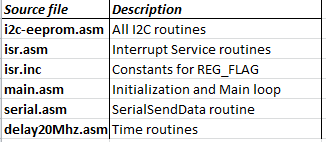
The source was written using _assembly relocatable code_; relocatable code was described in a [previous article](https://www.t3ch.it/pic18-guide-assembling-linking-and-programming-linux); here is a brief description of what every source file does:
The files can be downloaded in the attachment below; just extract the tarball and compile/build the sources with the accompanying executable picbuildprog.sh as described in the above article.

