Table of Contents
PIC18: PCF8563 I2C Real Time Clock Calendar
 The Freedom II demoboard includes also a PCF8563 I2C Real Time Clock Calendar (RTCC); let's learn how to use it to display time and date and set an alarm.
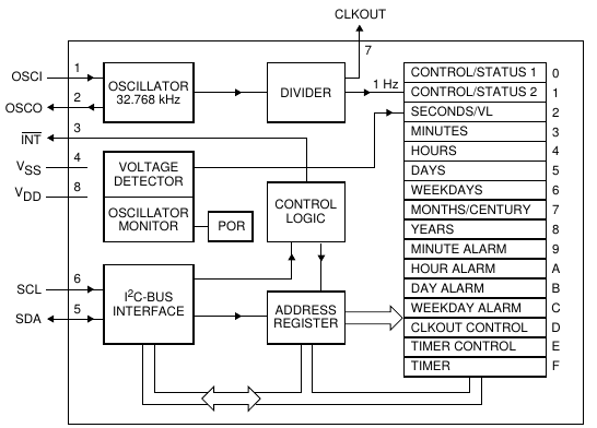
As soon as the RTCC is powered on it begins keeping time and date, starting from 00:00 (hh:mimi:ss) and from 00/00/00 (dd/momo/yy); the chip makes available those data thanks to a bunch of _registers_, which can be seen on the right of the below image:
So to read date and time we could just create a loop that does I2C sequential reads (see previous article on I2C) towards the PCF8563 and then display the values on an LCD; while it certainly can be done, it is quite an inefficient way to use the PIC, because it has to continually poll the RTCC. What we are going to do instead is using the RTCC interrupts to tell the PIC when the time/date have changed (or an alarm threshold has been reached) so that it can efficiently do the I2C reading.
RTCC Interrupts
As seen in the above diagram pin 3 (INT) is active low and is activated whenever a timer or alarm interrupt is raised; PORTB2 in the Freedom is connected to it so that we can use its INT2 External to capture an RTCC interrupt event; let's see how we can do this in practice.
Set RTCC for Timer and Alarm interrupts
The PCF8563 has to be _prepared_ to raise interrupts; that's done by the I2C_RTCCtrlStatus2Set and I2C_RTCTimerInit routines.
I2C_RTCCtrlStatus2Set modifies CtrlStatus2 register (01h), by clearing AF (alarm flag) and TF (timer flag) bits and setting AIE (Alarm Interrupt Enable) and TIE (Timer Interrupt Enable) bits:
I2C_RTCCtrlStatus2Set
  ; Setup I2C registers for Timer and Alarm Interrupt:
  call I2C_Start
  movlw litRTCWR
  call I2C_SendSSPBUF
  movlw 0x01
  call I2C_SendSSPBUF
  movlw 0x03		; Set TI, timer and alarm flags cleared, timer interrupt enabled
  call I2C_SendSSPBUF
  call I2C_Stop
  return
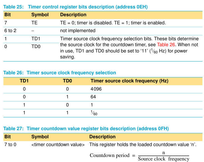
I2C_RTCTimerInit operates on Timer Control register (0Eh) by setting TE bit (Timer Enable) and the timer frequency to 64Hz:
I2C_RTCTimerInit
call I2C_RTCCtrlStatus2Set
; Load other I2C:RTC registers
call I2C_Start			; I2C Start
movlw litRTCWR
call I2C_SendSSPBUF
movlw 0x0E 		; Register Timer Countdown (0x0E)
call I2C_SendSSPBUF
movlw 0x81		; Timer Enabled, 64Hz clock frequency
call I2C_SendSSPBUF
movlw 0x20		; Load register 0x0F (Timer Countdown) with value 0x20 (dec. 32)
call I2C_SendSSPBUF
call I2C_Stop
; set alarm time
call I2C_Start			; I2C Start
movlw litRTCWR
call I2C_SendSSPBUF
movlw 0x09 		; Register
call I2C_SendSSPBUF
movlw 0x08		; AE = 0: alarm enabled; 8 minutes
call I2C_SendSSPBUF
call I2C_Stop
return
What a 64HZ clock frequency means is that the Timer Countdown register (0Fh), loaded with an arbitrary value of 0x20 (dec. 32, see above), decreases of one unit every 1/64s and when it reaches 0 a timer interrupt is generated. This occurs every 1/2s (32/64), so every half a second the RTCC warns the PIC that the time _could_ be changed.
Alarms
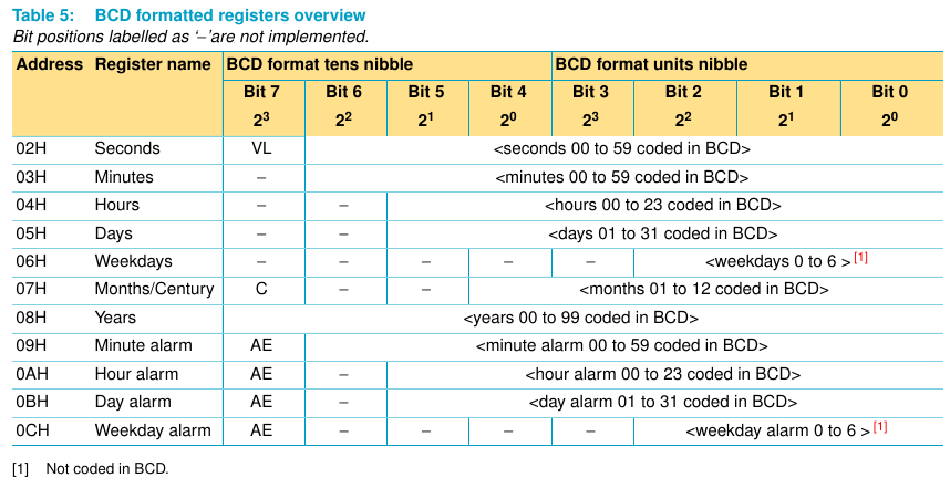
Let's take a look at the registers from 09h to 0Ch:
An alarm interrupt is raised whenever all alarm enabled conditions are met; that means that if we set the register bits AE (alarm enable) for hours and minutes, for instance, and we put the BCD values 4 and 32 an alarm will raise only when it's 4:32 (both enabled conditions are evaluated).
Interpreting the interrupts
Now the PIC starts to see interrupts for timer and alarm coming from the RTCC; in isr.asm this is taken care of by this piece of code:
IsrINT2
  bcf INTCON3,INT2IF
  bsf REG_FLAG,INT2ExtInt	   ; Set flag INT2ExtInt in the custom register REG_FLAG, which is checked in main.asm
  goto EndIsr
which sets the flag INT2ExtInt, checked in main.asm:
; check RTC interrupt
btfss REG_FLAG,INT2ExtInt	   ; check if there's an interrupt from INT2
goto EndMain			   ; NO: goto EndMain
call I2C_RTCCtrlStatus2Read	   ; YES: read CtrlStatus2
The sub I2C_RTCCtrlStatus2Read, inside i2c-rtcc.asm reads RTCC Control/Status 2 (01h), puts its value into RTCReg0x01 and goes back to main, where only bits 2 and 3 (TF and AF: timer and alarm flags) are extracted using a mask. Then the program jumps to two different routines, on the evaluation of the AF or TF flag:
movlw b'00001100'		; use mask to get only AF and TF flags of CtrlStatus2
andwf RTCReg0x01,F		; and mask with RTCReg0x01 and leave the result in the register
btfsc RTCReg0x01,3		; check if bit 3 (AF) is clear
call RTCAlarmInterrupt	; NO: it is set, so call sub I2C_RTCAlarmInt
btfsc RTCReg0x01,2		; check if bit 1 (TF) is clear
call RTCTimerInterrupt	; NO: it is set, so call sub I2C_RTCTimerInt
Then the normal, not interrupted, state is restored by:
- calling I2C_RTCCtrlStatus2Set sub, which clears AF and TF bits in the RTCC (see above)
- clearing REG_FLAG,INT2ExtInt, so that the next interrupt can be handled.
BCD to byte conversion to view values onto LCD display
Once a Timer interrupt is raised sub RTCTimerInterrupt (in main.asm) is called:
RTCTimerInterrupt
call RTCView				; Timer Interrupt occurred: view RTC values on LCD
RTCView sub does the following:
RTCView
call I2C_RTCRead	; call sub that reads RTC values via I2C
call I2C_BCD2BYTE	; call sub that converts BCD values to a byte
						;  in order to display them onto the LCD
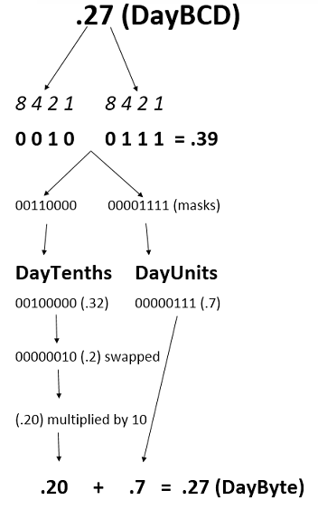
The values read by I2C_RTCRead are BCD ones and saved into file registers named SecondsBCD, MinutesBCD and so on; BCDs are representations of numbers in which each digit is a 4bit (one nibble) number. So for instance the BCD decimal number 27 is 0010 (2) 0111 (7) , which is .39 in normal (not BCD) decimal format.
We have to convert BCDs before viewing them on the LCD; that's what I2C_BCD2BYTE does.
The sub splits the BCD values into two parts, by using proper masks, one for the units, the other for the tenths. Then tenths are swapped, multiplied by 10 and added to units to obtain the byte value to be displayed onto the LCD:
I2C_BCD2BYTE
; Obtain values from BCDs
  movlw b'00001111'	; use mask
  andwf DayBCD,W	; AND BCD value and mask
  movwf DayUnits	; copy value to register
  movlw b'00110000'	;use mask
  andwf DayBCD,W	;AND BCD value and mask
  movwf DayTenths	;copy value to register
  swapf DayTenths,F	;swap the result into the lower nibble
  movlw .10		; multiplier value
  mulwf DayTenths		; DayTenths * 10
  movff PRODL,DayByte	; copy the low byte result of the previous multiplication to DayByte
  movf DayUnits,W		; copy DayUnits to W
  addwf DayByte,F		; copy W (DayUnits) to DayByte
Set date and time
Now that the display is showing date and time by using interrupts, wouldn't it be cool to also be able to set date, time and alarm values? To do that we could use the Freedom II board buttons in this way:
- BT1: toggles date/time modification status
- BT2: increases current date/time value (hours,minutes,seconds,…)
- BT3: decreases current date/time value (hours,minutes,seconds,…)
- BT4: skips to next date/time value
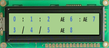
So to tell the PIC we want to modify the values we have first to press BT1 in order to activate the modify mode; then we can move to a specific position with BT4, according to the following scheme:
so pressing BT4 once means moving to position 1 (minutes), once again to move to position 2 (seconds), then 3 (day), 4 (month), 5 (year), 6 (alarm hours), 7 (alarm minutes), 8 (alarm day) and lastly back to 0 (hours); the values really shown on AE positions are _0_ when alarm is _enabled_ or _1_ when it is disabled.
Then the values can be increased and decreased with BT2 and BT3 respectively; the routines for these buttons consider different minimum and maximum values, depending on the value to be changed: a maximum value of 23 for hours, 59 for minutes and seconds… a minimum value of 01 for month, 01 for day and so on. Actually the maximum values for alarms are different; for instance the maximum value for minutes is 60, which means alarm disabled for that particular alarm.
Both routines end in the same way:
call I2C_BYTE2BCD	; Convert BYTES to BCDs
call I2C_RTCWrite	        ; Write BCDs to RTC
the sub I2C_BYTE2BCD, which is inside i2c-rtcc.asm converts the changed byte value to a _BCD_. Let's see how to achieve that.
Byte to BCD conversion before writing values to RTCC registers
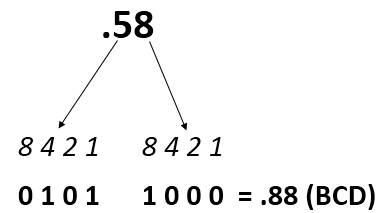
Say we have just changed the byte value for seconds to 58; we have to convert it in BCD, because RTCC registers expect BCD numbers only. The BCD representation of .58 is .88; this last value has to be saved into the seconds register of the RTCC; with BCDs the first digit (5) goes into the upper nibble and the second (8) into the lower nibble:
So 58 has to be split into 5 and 8; that's a division by ten, in which 5 is the result (quotient) and 8 is the remainder. And that's taken care of by the aptly named DivisionBy10 sub (inside math.asm); then quotient and remainder are properly handled into I2C_BYTE2BCD to form the SecondsBCD (.88), which is written, along with the other BCDs, to the RTCC by the I2C_RTCWrite sub.
DISCLAIMER: This is an unfinished project. I got stuck at a certain point and didn't have time or energy to debug and complete it; the code was starting to become really convoluted and needs refinement, to say the least… All the interrupt parts works; the challenging part was the one which sets date and time. BT4 doesn't skip smoothly to the next value, plus there is no way to determine the actual position of the value to be changed. AE bits are overwritten.

